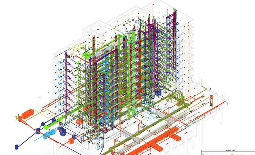
Scan to BIM, Point Cloud to BIM & As-Built Modeling Services
Convert registered laser-scan and point-cloud data into coordinated architectural, structural and MEPFP BIM models, 2D as-built drawings and existing-condition documentation for renovation, retrofit, refurbishment, reconstruction and facility-planning projects.

Digital Existing-Condition Models for Renovation, Coordination and Asset Documentation
Scan-to-BIM converts captured spatial data from an existing building, plant or infrastructure asset into structured BIM geometry and associated project information.
Structural Drafting Group supports laser-scanning companies, surveyors, property owners, architectural firms, engineering consultants, MEP teams, contractors and construction managers with point-cloud processing, Revit modeling, 2D as-built drawings, multidisciplinary coordination and model-based planning documentation.
Architectural, Structural and MEPFP Existing-Condition Models
The published service scope covers all three primary building-modeling disciplines. Elements are included only when they are visible, identifiable and within the agreed project scope.
Architectural Scan-to-BIM
Existing architectural geometry modeled from visible point-cloud conditions and agreed classification requirements.
- Exterior and interior walls
- Floors, ceilings and roof geometry
- Doors, windows and openings
- Stairs, railings and major built-in elements
- Facades, site context and landscape features
- Rooms, levels and agreed asset information
Structural Point-Cloud Modeling
Visible structural systems represented for existing-condition documentation, coordination and engineering review.
- Columns, beams and framing members
- Slabs, foundations and major concrete elements
- Trusses, bracing and structural supports
- Structural openings and penetrations
- Member annotations and agreed parameters
- Interfaces with architecture and MEP systems
MEPFP Scan-to-BIM
Visible mechanical, electrical, plumbing and fire-protection systems modeled to the agreed size and detail threshold.
- Ductwork and major HVAC equipment
- Pipes, fittings and plumbing systems
- Electrical panels and junction boxes
- Cable trays and visible containment
- Air terminals and fire sprinklers
- Service coordination and clash-review models
From Point-Cloud Preparation to Model, Drawing and Coordination Outputs
The useful legacy scope is retained and reorganized into clear production and project-use categories.
Point-Cloud Review and Preparation
Review source files, registration status, coordinates, scan coverage, units, clipping regions and data organisation before modeling.
Review Source DataParametric As-Built BIM Models
Create Revit elements from visible scan conditions using agreed families, categories, parameters, naming and model requirements.
View BIM Services2D As-Built Drawings
Produce plans, reflected ceiling plans, sections, elevations, roof plans and details with agreed dimensions, annotations and layers.
Discuss As-Built DrawingsModel-to-Point-Cloud Comparison
Review modeled geometry against the source cloud and document deviations, unresolved conditions and areas requiring clarification.
Discuss Verification ScopeBIM Coordination and Clash Review
Coordinate modeled existing conditions with proposed architecture, structure or MEP systems and support Navisworks-based issue review.
Explore BIM CoordinationRenovation and Retrofit Models
Develop existing-condition information for refurbishment, renovation, reconstruction, additions and building-system upgrades.
Discuss Retrofit ModelingDemolition and Existing-Condition Documentation
Support demolition planning and design comparison by separating known existing elements from proposed or removal scope.
Review Documentation NeedsQuantity and Asset-Information Support
Classify visible modeled elements to support agreed schedules, take-offs, feasibility studies, planning and facility-information requirements.
Define Information OutputsInfrastructure Point-Cloud Modeling
Convert suitable scan data for tunnels, bridges, roads, stations and other infrastructure assets into agreed BIM or CAD deliverables.
Discuss Infrastructure ScopeDefine Survey Quality, Modeling Scope and Acceptance Criteria Before Production
A reliable proposal needs more than a point-cloud file. The project team should define what was scanned, what must be modeled, how accurately and for what downstream purpose.
Confirm scan locations, registered data, survey control, coordinate system, units, orientation and source-file organisation.
Identify buildings, floors, rooms, disciplines, visible elements, size thresholds, exclusions and required metadata.
Define the required model development and information fields for each element category and project use.
Agree geometric tolerances, sample checks, deviation-reporting rules and treatment of irregular or damaged conditions.
Confirm Revit version, linked or federated model structure, CAD sheets, NWC/IFC exchange, naming and delivery milestones.
Specify Model Development Without Confusing It with Survey Accuracy
The legacy page identifies modeling across LOD 100–500. The actual requirement should be assigned by discipline, element and intended use rather than applying one label to the complete model.
Conceptual and Approximate Existing Conditions
General massing, major spaces, approximate systems or simplified elements for early planning and feasibility use.
Defined Geometry for Documentation
Elements represented with agreed size, shape, location and orientation suitable for coordinated existing-condition drawings.
Interfaces or Detailed Project Requirements
Additional interfaces, supports, connections or component detail included only where visible, required and supported by the source data.
Verified Record-Model Requirements
Project-specific verified record information requires an agreed verification process and should not be inferred solely from an incomplete point cloud.
Document What the Scan Can—and Cannot—Support
Model reliability depends on the capture environment and the acceptance rules agreed for irregular existing conditions.
Use Scan-to-BIM Information Across Planning, Design and Asset Workflows
The model use determines the required scan coverage, disciplines, detail, data, tolerance and verification method.
Renovation and Refurbishment
Document existing rooms, structure and services to support new layouts, upgrades and coordinated retrofit design.
Design Validation and Comparison
Compare captured conditions with previous drawings, BIM models or proposed design geometry and document significant differences.
Clash and Interference Review
Coordinate proposed architectural, structural or MEP systems against modeled existing conditions before site execution.
Demolition and Reconstruction Planning
Support separation of existing, retained, removed and proposed elements through structured models and drawings.
Quantity and Budget Support
Use classified visible elements for agreed quantity take-offs, feasibility studies and early budget-planning inputs.
Facility and Asset Documentation
Create an organised baseline for existing-condition records, asset tagging and future maintenance or modification workflows.
Heritage and Complex-Geometry Records
Represent irregular facades, historic spaces and complex geometry with project-defined simplification and tolerance rules.
Infrastructure Documentation
Develop model or CAD information for suitable bridge, road, tunnel, station and utility scan datasets.
Provide Registered Scan Data and a Clear BIM Modeling Standard
The published legacy page correctly identifies point-cloud data and company standards as essential inputs. A complete project setup should define additional survey, model and QA information.
INTypical Source Inputs
Source data may come from common Leica, FARO, RIEGL or other laser-scanning and survey workflows, subject to an agreed transferable format.
OUTTypical Deliverables
Outputs can support existing-condition review, design coordination, planning, construction documentation and facility records.
Check the Source Cloud, Modeled Geometry, Information and Deliverables
Quality review should sample the model against the source data and record limitations, not rely only on visual appearance.
Point-Cloud and Setup Check
Confirm file integrity, registration, units, coordinates, orientation, scan coverage, clipping, linked data and current source revision.
Geometry and Tolerance Check
Compare selected walls, floors, columns, beams, ducts, pipes and equipment against the cloud using agreed tolerance rules.
Discipline and Information Check
Review categories, families, levels, systems, parameters, classifications, naming, minimum object size and agreed model completeness.
Drawing and Delivery Check
Verify views, dimensions, annotations, sheets, linked models, warnings, coordinates, file versions, issue status and limitation notes.
A Controlled Workflow from Registered Point Cloud to Approved Outputs
The workflow is adapted to individual buildings, campuses, plants, infrastructure assets, multidisciplinary scope and phased scan datasets.
Scope & Data Review
Confirm project use, scan files, coverage, coordinates, disciplines, elements, tolerance, LOD/LOI and deliverables.
Project & Model Setup
Establish templates, levels, grids, coordinates, worksets, linked clouds, file structure and modeling rules.
Point-Cloud Modeling
Develop architectural, structural and MEPFP elements according to visible data and agreed requirements.
QA/QC & Coordination
Compare geometry with the cloud, review information, document occlusions and coordinate discipline interfaces.
Drawing & Model Delivery
Issue agreed BIM, CAD, coordination and as-built outputs with assumptions, limitations and revision status.
Scan-to-BIM Support for Buildings, Plants and Infrastructure
The current page identifies scanning companies, surveyors, owners, architects, MEP engineers, contractors and construction managers as primary users of point-cloud modeling services.
Software and Exchange Formats Defined Around the Project Workflow
The current service page identifies Revit and CAD outputs, laser-scanner data and Navisworks coordination as central parts of the Scan-to-BIM workflow.
Confirm source-cloud format, Revit version, coordinate system, units, worksharing method, linked model structure, export settings and software versions before work begins. Device brand alone does not define data quality or compatibility.
Scan-to-BIM Connected to Architectural, Structural and MEP Documentation
The service sits within the wider BIM hierarchy, allowing existing-condition models to connect with CAD-to-BIM, discipline modeling, coordination and construction documentation.
Architectural, structural and MEPFP elements developed within an agreed project model structure.
Revit models, CAD drawings, plans, sections, elevations, coordination views and agreed exchange files.
LOD, information, tolerance, categories, file standards and source limitations reviewed explicitly.
Capacity for individual structures, multidisciplinary buildings, plants, campuses and infrastructure datasets.
Continue to BIM, CAD Conversion or Discipline Modeling Services
These links follow the current website’s BIM service hierarchy and related engineering pathways.
Scan-to-BIM and Point-Cloud Modeling FAQs
Common questions about scan data, Revit modeling, LOD, accuracy, disciplines, outputs, occlusions and required project information.
What is Scan-to-BIM?
Does the service include on-site laser scanning?
Which disciplines can be modeled?
Can models be delivered from LOD 100 to LOD 500?
Is LOD the same as model accuracy?
Can hidden or concealed elements be included?
Which input and output formats are supported?
What information is needed for a quotation?
Need a Revit As-Built Model from Laser-Scan or Point-Cloud Data?
Share representative scan data, registration details, project area, required disciplines, LOD/LOI, tolerance, Revit version, drawing requirements and schedule. Our BIM team will review the Scan-to-BIM scope.