Piping Design, Engineering, 3D Modeling & Drafting Services
Integrated process and utility piping documentation—from PFD and P&ID development, plot plans and equipment layouts to 2D/3D piping models, isometrics, supports, stress-analysis support, material take-offs, fabrication drawings and as-built records.
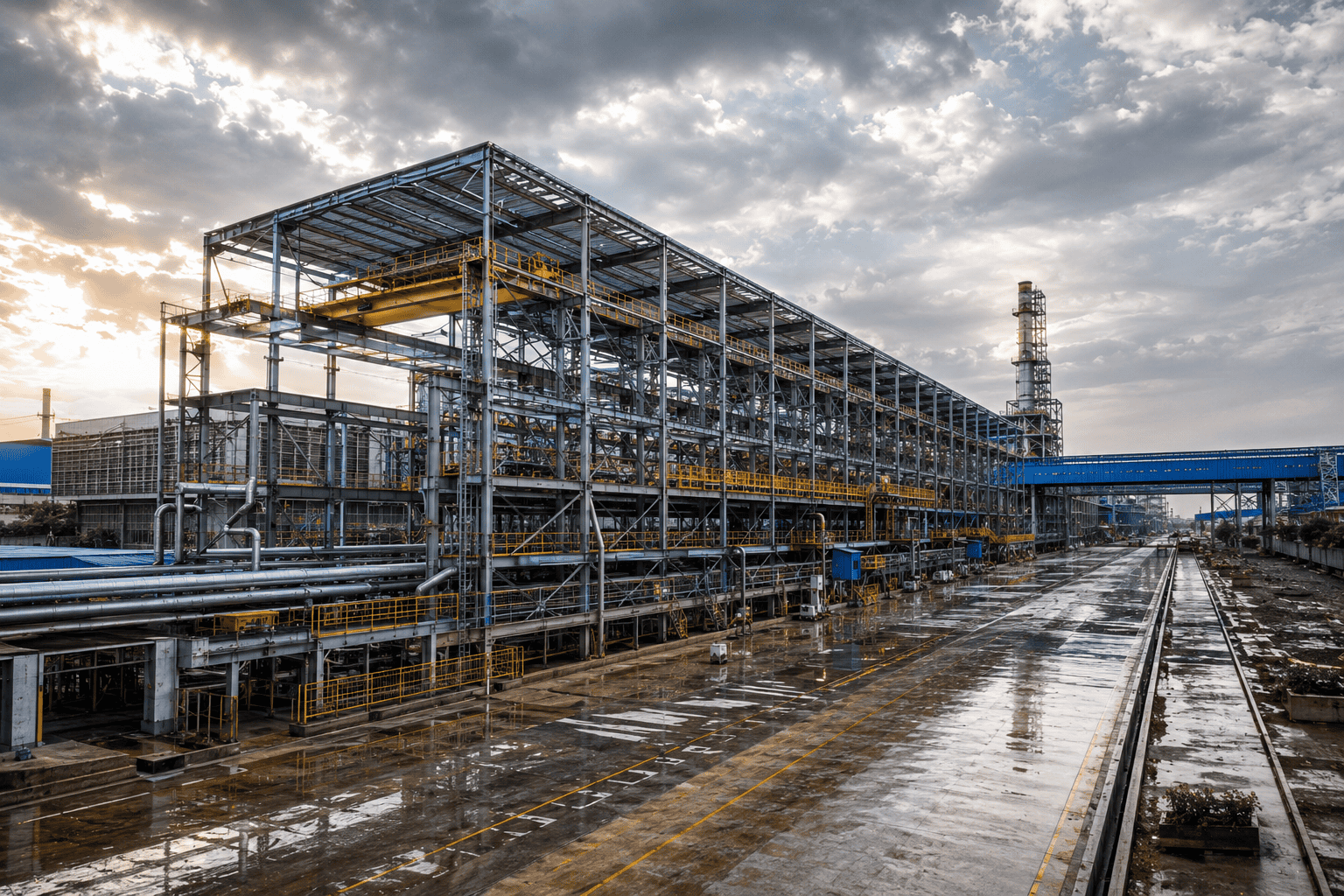
Piping Documentation for Process Plants, Utilities and Packaged Systems
Piping engineering converts process requirements and equipment information into a coordinated system of diagrams, specifications, layouts, models, calculations and construction documents.
Structural Drafting Group supports EPC, EPCM, OEM, PMC, plant-owner, equipment-supplier and specialist-contractor workflows with conceptual routing, pipe sizing inputs, plot plans, equipment arrangements, 2D and 3D layouts, P&IDs, isometrics, supports, material take-offs and controlled record updates.
From Conceptual Routing to Detailed Construction Documentation
The useful legacy service scope is retained and reorganized into distinct engineering and documentation categories.
PFD and P&ID Development
Process-flow and piping-and-instrumentation diagrams developed or updated from approved process data, equipment information, line lists, valves and control requirements.
Discuss Process DocumentsPiping Design Criteria & Specifications
Documentation of approved design conditions, piping classes, materials, components, insulation, painting and project-specific drafting requirements.
View Mechanical EngineeringPlot Plans & Equipment Layouts
Site master plans, plot plans, equipment arrangements, access zones, elevations and civil-interface information coordinated from approved inputs.
Review Plant Layout Scope2D Piping Layouts
Plan, elevation, section and detail drawings showing approved routes, equipment nozzles, valves, branches, elevations and support locations.
Explore Detailed Drafting3D Piping & Plant Modeling
Intelligent or geometric models of equipment, piping, structures, racks, access and multidisciplinary interfaces using agreed coordinates and specifications.
Explore BIM ServicesPiping Isometrics & Spool Drawings
Fabrication and installation documents showing dimensions, components, welds, branches, supports, testing notes and approved material information.
Discuss Isometric ProductionPipe Rack & Support Documentation
Rack arrangements, support locations, standard or custom support drawings and structural interfaces based on approved loads and support philosophy.
Coordinate Structural DetailingStress-Analysis Model Support
Geometry, line data, operating cases, support information and design revisions prepared for qualified flexibility and stress-analysis workflows.
Discuss Analysis InputsMaterial Take-Offs & As-Builts
Pipe, fitting, valve, flange, support, insulation and painting quantities plus approved field changes and record-document updates.
Review MTO or As-Built ScopeKeep Process, Layout, Model and Fabrication Information Connected
Each piping document communicates a different layer of information. A controlled source hierarchy helps prevent line, equipment, specification and quantity conflicts.
Design conditions, flow requirements, equipment, operating cases, control intent and approved system boundaries.
Line numbers, piping classes, valves, instruments, equipment connections, drains, vents and control relationships.
Plot plan, equipment orientation, routes, access, elevations, maintenance zones and multidisciplinary interfaces.
Approved operating cases, restraints, movements, support locations and analysis-driven routing modifications.
Isometrics, spool drawings, support details, weld information, material take-offs and record documentation.
Process, Utility, Hygienic and Specialized Piping Systems
System materials, jointing, cleaning, insulation, pressure, slope and quality requirements vary significantly by service.
Industrial Process Piping
Documentation for approved process, thermal and energy systems.
- Oil, gas and petrochemical piping
- Boiler and thermal-fluid piping
- Steam, condensate and utility systems
- High-temperature or critical lines
Utility and Mechanical Piping
Plant and facility services routed around equipment and building constraints.
- Compressed-air systems
- Chilled- and condenser-water piping
- Heating and cooling systems
- Vacuum and laboratory-gas services
Hygienic and Special-Service Piping
Systems requiring project-specific cleanliness, containment or installation controls.
- Food-grade and hygienic piping
- Pharmaceutical and biomedical systems
- Double-jacketed piping
- CO₂, N₂ and specialist-gas systems
Organize Calculations and Analysis Inputs Around Approved Process Data
Engineering calculations require qualified responsibility and should use the governing operating, design, upset, start-up, shutdown, wind, seismic and occasional cases.
Pipe Sizing & Pressure-Drop Inputs
Coordinate approved flow, fluid-property, velocity, pressure, temperature and allowable-pressure-drop criteria for responsible calculation and review.
Network & Transient Analysis Inputs
Prepare line, valve, equipment and boundary-condition data for qualified hydraulic, network, surge or transient-analysis workflows.
Stress & Flexibility Analysis Support
Develop or update piping geometry, temperatures, pressures, materials, restraints, supports and load cases for responsible analysis.
Support and Equipment-Load Coordination
Document approved reactions, movements, nozzle-load information, support requirements and structural interfaces.
Engineering, Model, Construction and Material Documentation
The deliverable register should define project stage, responsibility, document status, software, format and intended use.
Process & Engineering Documents
PFDs, P&IDs, line lists, valve lists, data sheets, design criteria, piping classes and approved engineering notes.
Plant Layout & 3D Models
Site plans, plot plans, equipment layouts, piping arrangements, 3D models, orthographic drawings and coordination views.
Fabrication & Installation Drawings
Isometrics, spool drawings, support details, nozzle-orientation drawings and approved welding or testing references.
Material & Record Outputs
MTOs, BOMs, valve and component summaries, insulation or painting quantities, redlines and verified as-built records.
Define the Process Basis, Equipment Data and Piping Responsibility Before Production
The controlling documents, design stage, line-list status, specifications, analysis responsibility, coordinates and required outputs should be agreed during project setup.
INTypical Source Inputs
Accurate piping documentation relies on approved process, mechanical, civil, structural and instrumentation information.
OUTTypical Deliverables
Outputs can support design review, procurement, fabrication, construction, commissioning, maintenance and records.
Check Line Data, Equipment Interfaces, Models and Isometrics
Quality review is structured around the approved process information and the intended use of each document.
Process & Line-Data Check
Confirm line numbers, design conditions, piping classes, equipment, valves, instruments, drains, vents and document revisions.
Layout & Constructability Check
Review equipment nozzles, routes, slopes, access, maintenance, clearances, rack interfaces and installation constraints.
Model, Stress & Support Check
Compare routing, restraints, support locations, movements, analysis comments and structural connection information.
Isometric & Material Check
Verify dimensions, components, welds, line data, supports, notes, quantities, drawing status and approved revisions.
A Controlled Workflow from Process Information to Construction Outputs
The workflow is adapted to conceptual engineering, detailed design, plant revamps, skid packages, point-cloud conversion or as-built documentation.
Scope & Design-Basis Review
Confirm systems, process data, source files, responsibilities, codes, software, deliverables and milestones.
Process & Layout Planning
Organize P&IDs, line data, equipment, plot plans, routing philosophy, specifications and coordinates.
Modeling & Detailed Drafting
Develop routes, layouts, models, isometrics, supports, material data and required engineering documents.
Analysis, Coordination & QA/QC
Review stress inputs, supports, nozzles, clashes, access, constructability, quantities and comments.
Issue & Lifecycle Updates
Release agreed outputs and incorporate approved design, vendor, construction or verified field changes.
Piping Engineering for Process, Utility and Infrastructure Systems
Fluid properties, hazards, cleanliness, pressure, temperature, materials, inspection and approval requirements vary by sector.
Software Selected Around the Plant-Design and Engineering Workflow
The existing page lists a broad piping and plant software environment for diagramming, modeling, drafting and analysis.
Confirm the required software version, database configuration, piping specifications, coordinate system, catalogues, model intelligence, exchange formats and analysis responsibility before work begins. Software output does not replace engineering verification.
Piping Documentation Connected to Mechanical, Structural and MEP Services
Piping routes, equipment, racks, supports and utilities can be coordinated within the wider engineering-documentation environment.
Support from PFDs and P&IDs through layouts, models, analysis inputs, isometrics and material outputs.
Equipment nozzles, skids, rotating systems, vessels, exchangers and plant interfaces reviewed across documents.
Pipe racks, support locations and approved reactions coordinated with structural detailing requirements.
Capacity for individual lines, packaged skids, complete facilities, revamps and recurring workloads.
Continue to the Relevant Mechanical, Drafting, MEP or BIM Service
These internal links connect the Piping Design page with the established website hierarchy.
Piping Design and Engineering FAQs
Common questions about scope, P&IDs, 3D models, isometrics, stress analysis, MTOs, software and professional responsibility.
What is included in Piping Design Services?
What is the difference between a P&ID and a piping layout?
Can a complete 3D plant and piping model be developed?
Can piping isometrics and material take-offs be generated?
Do you provide piping stress analysis?
Can existing plants be modeled from point clouds or field information?
Which software platforms are supported?
What information is needed for a quotation?
Need P&IDs, 3D Piping Models, Isometrics, Supports or Plant Documentation?
Share the process basis, PFDs or P&IDs, line list, equipment information, piping specifications, required project stage, software environment, deliverables and schedule. Our team will review the piping engineering and drafting scope.